The Raspberry Pi Pico board
MicroPythonMCU.RPi_Pico is a replica of the Raspberry Pi Pico board: the same programmable microcontroller as the MCU block — same Python program, same machine/time API, same parameters —, but with the real pinout of the board (40 pins) and its power supply: USB connector, VBUS, VSYS, 3.3 V regulator, 3V3(OUT).
Which one to choose?
MCU: a simplified microcontroller, 8 general-purpose pins, ideal and implicit supply. The simplest way to learn programming, and for circuits where the supply is not the topic.RPi_Pico: to wire as on the real board (pin numbers, UART/I2C multiplexing, ADC on GP26-GP28), and to study the power supply: battery life, consumption, power-on, voltage drop.
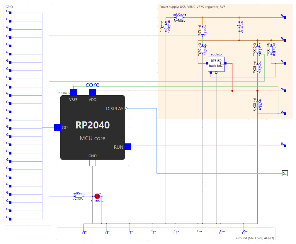
Both blocks contain the same programmable core (core, an Internal.McuCore component: the RP2040 and its program). Opening the internal diagram of the Pico (Diagram tab) shows this core wired to the USB connector, the Schottky diode, the regulator, the sensing dividers and the LED, as on the board. The icon has the real proportions of the board (21 × 51 mm, pins at a 2.54 mm pitch); a lightning bolt on the USB connector shows that it is supplied by the cable (usbConnected).
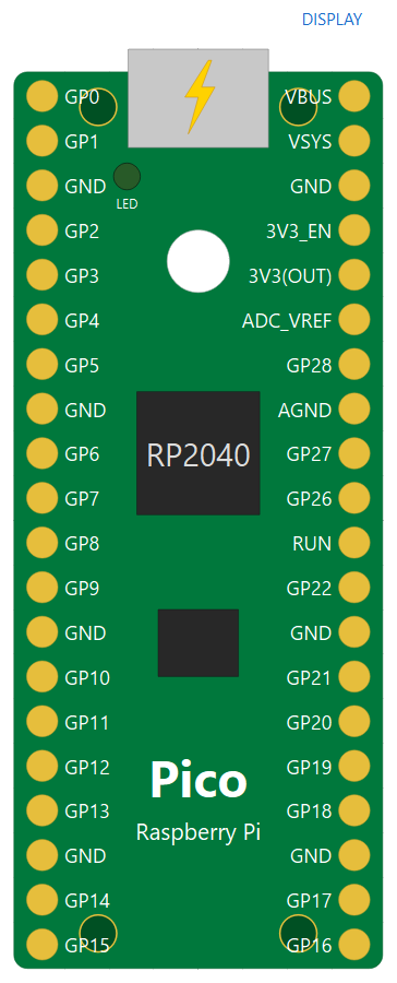
Pinout
Top view, USB connector at the top, like the real board. The connector names follow the silkscreen; three are adapted, since a Modelica name can neither start with a digit nor be repeated.
| Connectors | Physical pins | Role |
|---|---|---|
GP0 … GP22 |
1-29 (left and right sides) | Inputs/outputs: Pin, PWM, UART, I2C according to the RP2040 multiplexing |
GP26, GP27, GP28 |
31, 32, 34 | The three analog inputs: ADC(0), ADC(1), ADC(2) |
GND_3, GND_8, GND_13, GND_18, GND_23, GND_28, GND_38 |
3, 8, 13, 18, 23, 28, 38 | Grounds (silkscreen "GND"), all connected together. Connect at least one to the ground of the circuit (Ground) |
AGND |
33 | Analog ground, connected to the others |
VBUS |
40 | 5 V of the USB connector (usbConnected), or input of an external 5 V supply |
VSYS |
39 | Main input of the board, 1.8 to 5.5 V: supplied by VBUS through a Schottky diode, or directly by a battery |
V3V3_EN |
37 | Silkscreen "3V3_EN": enable of the regulator, pulled up to VSYS; grounded, the regulator stops |
V3V3 |
36 | Silkscreen "3V3(OUT)": 3.3 V output of the regulator, to supply external circuits |
ADC_VREF |
35 | ADC reference: the 3.3 V filtered through 200 Ω on the board |
RUN |
30 | RP2040 enable, pulled up to 3.3 V; grounded, the RP2040 is stopped (see below) |
Display0 |
— | Logical link to an educational display, at the top of the icon. It does not exist on the real board: it is the same teaching tool as on MCU |
The on-board LED (Pin("LED") or Pin(25)) is drawn at its place on the icon. The internal pins of the board are available as on the real one: Pin(24) reads the presence of VBUS, ADC(3) (GPIO29) reads VSYS/3, ADC(4) the temperature sensor of the RP2040; Pin(23) (regulator mode) exists without effect.
Power supply
The board only runs its program while it is supplied. Three ways to do it, as on the real board:
- Through the USB cable (default,
usbConnected = true): 5 V onVBUS, nothing to wire. This is the board plugged into the computer. - Through
VSYS, typically one or two AA cells, withusbConnected = false. The regulator is a buck-boost: it delivers 3.3 V even whenVSYSis below (1.8 to 5.5 V). - Through
VBUSwith an external 5 V supply,usbConnected = false.
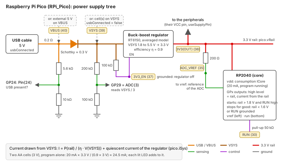
Block diagram of the power supply, with the numbers of the physical pins. The colours are those of the wires of the internal diagram of RPi_Pico in OMEdit.
In OMEdit, the internal diagram of RPi_Pico (Diagram tab) shows this wiring as modelled, with the same colours: the core core (RP2040), the USB, the diode, the dividers, the regulator, the ADC_VREF filter and the LED.
The regulator makes the 3.3 V rail from VSYS. It is an averaged model, without switching: the output is held at 3.3 V, and the current drawn from VSYS is the power delivered divided by the efficiency (eta, 0.9) and by the voltage of VSYS. The rail supplies the RP2040 and its flash (ICore, 20 mA), the pins — the current of an LED on an output is drawn from the rail, hence from the battery — and the 3V3(OUT) output.
Budget example, two AA cells (3 V): 20 mA × 3.3 V / (0.9 × 3 V) ≈ 24.5 mA drawn from the cells, program alone; a few milliamps more per lit LED.
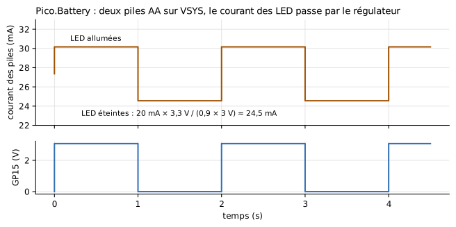
Pico.Battery: "courant des piles" = current of the cells, "LED éteintes / allumées" = LEDs off / on.
Power-on and power loss
- The program (
boot.py/main.pyor the script) starts at power-on: the first time the 3.3 V rail exceedsVPowerOn(1.8 V) withRUNhigh.time.ticks_ms()counts from this instant, not from the start of the simulation. With USB, this is at t = 0. - If the rail then falls below
VPowerOff(1.6 V) — empty battery,VSYScut,3V3_ENorRUNgrounded —, the program is stopped for good: its pins are released (high impedance), a timestamped warning appears in the log. The return of the supply does not restart it: the restart is not simulated. - A board that is never supplied runs nothing; the simulation ends normally.
Example: Pico.PowerUp, a ramp on VSYS.
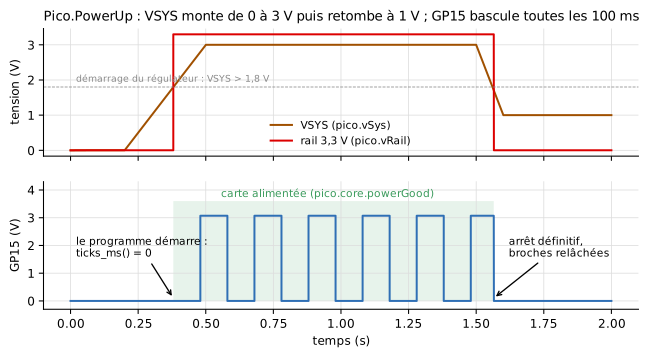
"démarrage du régulateur" = regulator start-up, "carte alimentée" = board supplied, "le programme démarre" = the program starts, "arrêt définitif, broches relâchées" = stopped for good, pins released, "temps" = time.
Supplying the peripherals from the board
The peripherals of the library (serial devices, radio modules, I2C peripherals, HX711) have an ideal internal supply by default. Checking their useSupplyPin parameter shows a VCC pin (bottom left of their icon): connect it to 3V3(OUT) of the board. Their high levels then follow the voltage they receive, and their consumption (IQ) is drawn from the board, hence counted in the battery budget.
MicroPythonMCU.RPi_Pico pico(usbConnected = false);
MicroPythonMCU.Peripherals.UartEchoDevice echo(useSupplyPin = true, IQ = 0.002);
equation
  connect(pico.V3V3, echo.VCC);   // 3V3(OUT) -> VCC
  connect(pico.GND_3, echo.GND);
Programming the Pico
The program is that of a real Pico running MicroPython. Compared with the MCU block, what changes follows the real board:
MCU |
RPi_Pico |
|
|---|---|---|
| Pins | GP0-GP7 |
GP0-GP22, GP26-GP28 |
ADC |
ADC(n) on any of the 8 pins |
ADC(0)-ADC(2) = GP26-GP28, ADC(3) = VSYS/3, ADC(4) (ADC.CORE_TEMP) = temperature; also ADC(Pin(26)). Elsewhere: ValueError |
| ADC reference | VOH |
ADC_VREF (filtered 3.3 V) |
UART, I2C |
tx/rx, scl/sda required, any pins |
RP2040 multiplexing (UART(0): TX on GP0, 12, 16 or 28…), default pins of the rp2 port when not given (UART(0): GP0/GP1, UART(1): GP4/GP5, I2C(0): SCL GP5/SDA GP4, I2C(1): SCL GP7/SDA GP6); I2C without an identifier takes that of its pins |
SoftI2C |
same controller | any pins, as on the board |
from machine import Pin, ADC, UART
uart = UART(1, baudrate=9600)        # TX GP4, RX GP5: default pins
vsys = ADC(3).read_u16() * 3.3 / 65535 * 3
temp = 27 - (ADC(4).read_u16() * 3.3 / 65535 - 0.706) / 0.001721
A pin that is not allowed for this peripheral raises the error of the rp2 port ("bad TX pin", "bad SCL pin"). The simulation has a single UART engine and a single I2C controller: UART(0) and UART(1) are both accepted, but only one at a time (likewise for I2C(0)/I2C(1)).
Parameters
The tabs of the MCU block are the same (script, execution time, file system, debugging, Electrical without VOH): see The MCU block. The high level of the outputs is the voltage of the 3.3 V rail. The Power supply tab is specific to the board:
| Parameter | Default | Group | Role |
|---|---|---|---|
usbConnected |
true |
USB | USB cable plugged in: 5 V on VBUS. Unchecked: supply the board through VBUS or VSYS |
VUsb |
5 V | USB | Voltage of the USB supply |
RUsb |
0.2 Ω | USB | Resistance of the USB cable and connector |
eta |
0.9 | Regulator | Efficiency of the 3.3 V regulator |
ICore |
20 mA | Consumption | Current drawn from the 3.3 V rail by the RP2040 and its flash while the board is supplied (pins excluded) |
VPowerOn |
1.8 V | Power-on | Rail voltage above which the RP2040 starts |
VPowerOff |
1.6 V | Power-on | Rail voltage below which a running RP2040 stops for good |
dieTemperature |
27 °C | Temperature sensor | Temperature of the RP2040, read by ADC(4) |
Variables to plot
| Variable | Content |
|---|---|
pico.GP0.v … |
Voltage of each pin |
pico.vSys |
Voltage of VSYS |
pico.vRail |
Voltage of the 3.3 V rail (3V3(OUT)) |
pico.iSys |
Current drawn from VSYS by the regulator |
pico.core.powerGood |
Board supplied (program started or ready to start) |
pico.builtinLed.… |
On-board LED |
For the current of a battery, put a CurrentSensor on the VSYS wire, as in the Pico.Battery example.
Further reading
- MicroPython quick reference of the rp2 port: the API as it runs on the real board; rp2 port general information;
rp2module (PIO, not simulated). - Raspberry Pi Pico datasheet: schematic, power supply ("Powering Pico" chapter), dimensions; pinout.
- RP2040 datasheet: pin multiplexing (GPIO functions), ADC and temperature sensor.
- Raspberry Pi documentation of the Pico boards.