LED and teaching displays
Simple components to see what the program does: an LED whose icon lights up according to the current flowing through it, and text displays connected to the microcontroller by a logical link (a 20x2 one, and two large screens that fill line after line).
Peripherals.LED
A two-pin light-emitting diode. Electrically, it is a diode with a smooth exponential characteristic and a 1.8 V threshold by default (red LED). Its icon goes from colorOff to colorOn according to the average current flowing through it: you see the LED light up when replaying the result in OMEdit, and PWM makes it look more or less bright.
Connectors
| Connector | Role |
|---|---|
p |
Anode, microcontroller pin side |
n |
Cathode, ground side |
Parameters
| Parameter | Default | Role |
|---|---|---|
Vknee |
1.8 V | Diode threshold voltage. About 2 V for a yellow or green LED, 3 V for a blue or white one |
IMax |
3.5 mA | Current at which the icon reaches its full colour. Display scale only, not a physical limit. The default matches an LED driven by a pin through 330 Ω |
colorOn |
{255, 0, 0} |
RGB colour of the icon at full brightness |
colorOff |
{90, 25, 25} |
RGB colour of the icon when off |
Typical wiring
As on a real board, a resistor limits the current: GP0 → 330 Ω resistor → LED p, n → ground. Wiring the LED straight to the pin works (the 100 Ω output resistance limits the current), but is not representative of a real circuit.
The current is plotted under led0.p.i (for an LED named led0).
Displays: Display, Display4x32, Display8x32
Three text displays which show on their icon the messages sent by the program with machine.Display(0).write(...). They display a result without having to set up a real serial or I2C link. All three are programmed and wired the same way; they only differ in size and in how messages follow one another.
| Component | Size | Scrolling |
|---|---|---|
Peripherals.Display |
2 lines of 20 characters | Each message is shown on line 1; the previous one moves down to line 2 |
Peripherals.Display4x32 |
4 lines of 32 characters | Like a terminal: each message is written under the last written line; once the screen is full, everything moves up by one line and the new message takes the bottom line |
Peripherals.Display8x32 |
8 lines of 32 characters | Like Display4x32 |
The large screens are handy to follow a history of measurements or states without opening the log.
from machine import Display
import time

screen = Display(0)
for i in range(10):
    screen.write("Reading %d: %d mV" % (i, 1650 + 10 * i))
    time.sleep_ms(100)
At the end, the 20x2 shows the last two readings (the most recent at the top), the 4x32 readings 6 to 9 and the 8x32 readings 2 to 9 (the most recent at the bottom).
Connector
| Connector | Role |
|---|---|
displayLink |
To connect to mcu.Display0. It is a logical link: it carries the text directly, with no voltage nor waveform |
Wiring
One wire, from the DISPLAY output of the microcontroller (mcu.Display0, above the MCU icon) to the input of the display (displayLink, on its left). No ground nor supply to wire for the display: the link is logical. The MCU keeps its own ground.
Several displays may be connected to the same Display0: they all receive every message. This is what Display.Large does, with a 20x2 (display), a 4x32 (screen4) and an 8x32 (screen8):
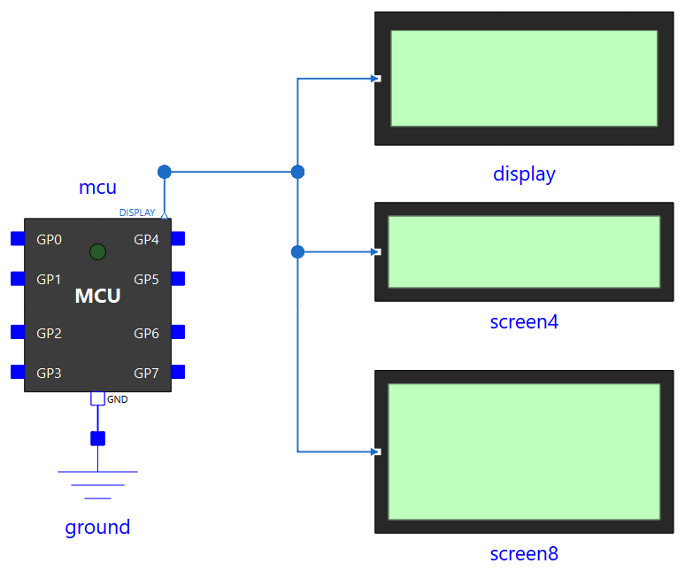
As text, in the Text view of OMEdit: connect(mcu.Display0, display.displayLink);, and likewise for screen4 and screen8.
Parameter
Display has no parameters. The two large screens have one:
| Parameter | Default | Role |
|---|---|---|
logReceived |
true |
Also prints every received message in the simulation log. Set it to false when several displays share Display0, so that each message is not logged twice |
Behaviour
- A message is one line sent by
write(), which is used likeprint()(see the API):write("a\nb")sends two messages. Several messages sent at the same instant (withoutsleep()in between) all arrive, in order: the 20x2 shows the last two, the large screens write them one under the other. - A message written at the very start of the program, before the first
sleep()(t = 0), is shown as well. The large screens start empty: the first message takes the top line. - A message longer than the line (20 or 32 characters) is cut on the icon, but appears in full in the simulation log. Messages are limited to 128 characters.
- Displayable characters: unaccented letters, digits and space, plus
! ' , - . ?on the 20x2 and! " # & ' ( ) * + , - . / : < = > ? _on the large screens. Others are shown as spaces. - The link is instantaneous: the message arrives at the very moment of the
write(), with no transmission delay. Write-only: the display never answers. - On the large screens, the text of the icon is stored in
textCode(ASCII codes, linei, columnjat index(i - 1)*32 + j) and the number of written lines infilled: both can be found in the results.
For a display connected by a real electrical link, see UartLcd20x2 (Serial devices) or the Grove LCD RGB display (I2C devices).
Examples: Display.Demo (one 20x2, two messages), Display.Large (the three displays on the same link), Weighing.Hx711Read.