Radio link
Peripherals.Radio provides transparent radio modules. Each one plugs into the UART of a microcontroller, and one wire, from antenna to antenna, joins the modules that can hear each other. What a program writes with machine.UART comes out of the UART of the other microcontroller, after going through the module's buffers, a fixed delay and a radio frame at the air data rate. The modulated signal (OOK, ASK, FSK or BPSK) is drawn for teaching purposes.
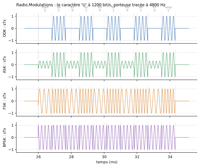
The character U (0x55) sent by the four transmitters of the Radio.Modulations example, at 1200 bit/s, with a carrier drawn at 4800 Hz. Above: the bits of the radio frame (start, 8 bits least significant first, stop). Figure labels in French.
Wiring
On the microcontroller side, this is the wiring of a serial device: two crossed wires and a common ground. On the radio side, a single wire between the antennas, which stands for the air.
| From | To | Direction |
|---|---|---|
TX pin of the program (e.g. GP0) |
RX of the module |
what the microcontroller sends |
TX of the module |
RX pin of the program (e.g. GP1) |
what the module received by radio |
GND |
GND |
common reference |
antenna of module A |
antenna of module B |
the air between the two modules |
The program is the one of a wired link: the module is transparent, there is no command or configuration to send. machine.UART only needs the same speed and format as the serial side of the module.
from machine import Pin, UART

uart = UART(0, baudrate=9600, tx=Pin(0), rx=Pin(1))   # same speed and format as the module: 9600 baud, 8N1
uart.write(b'PING 0\n')
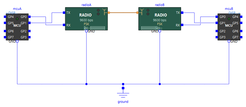
Several modules can share the same wire: a transmitter can thus broadcast to several receivers. Two independent links need two separate wires.
The module
RadioModem is a transparent module with every setting adjustable: air data rate very different from the serial speed, small buffers, delays, full duplex… to show what each one changes. Its defaults are inspired by the APC220 module: 434 MHz, 9600 baud on the serial side and 9600 bit/s on air, 256-byte buffers, half duplex. A real APC220 uses GFSK, close to FSK, the default modulation.
On the icon, while replaying a result with animation: the amber dot lights up during a transmitted radio frame, the cyan dot during a received one, and the two bars show how full the transmit and receive buffers are.
What a module does
- Each byte received from the microcontroller enters the transmit buffer. If the buffer is full, the byte is lost.
- It stays there at least
txDelay, then leaves on air as soon as the transmitter is free, in a UART-like frame (start, 8 bits, stop) at the air data rate, which may differ from the serial speed. - The module that hears the frame decodes it at its own air data rate. A wrong frame, for example because the two air data rates differ, is dropped, as a real module that checks its packets does.
- The received byte enters the receive buffer, stays there at least
rxDelay, then leaves on the UART towards the microcontroller.
A module only hears the transmitters tuned to its channel (same frequency, within half the channel width) and using the same modulation. In half duplex (the case of the APC220), it hears nothing while it transmits: a frame arriving during its own transmission is lost. If two modules transmit at the same time on the same wire, their frames jam each other and are lost (collision).
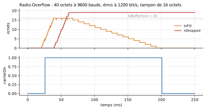
Radio.Overflow example: 40 bytes arrive at 9600 baud, but the module transmits them again at only 1200 bit/s. The 16-byte buffer fills up (txFill), then every byte arriving while it is full is lost (nDropped). A place is freed only when a radio frame leaves.
Masked synchronisation and drawn signal
The receiver does not demodulate the drawn signal. The antenna wire also carries the bit being transmitted, and the receiver decodes that bit, as a real serial receiver would. This is the masked synchronisation: demodulation is assumed perfect, with neither filter nor noise.
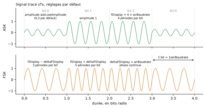
The modulated signal sTx is drawn with a scaled carrier, fDisplay, four times the air data rate by default. A real carrier (434 MHz) would have hundreds of millions of periods per second and could not be drawn. The nominal frequency fCarrier only decides which modules hear each other. The settings of the drawing (fDisplay, deltaFDisplay, askLowAmplitude) change nothing in what the other module receives: they only serve the curve.
| Modulation | A 0 | A 1 |
|---|---|---|
OOK |
no carrier | carrier |
ASK |
carrier of amplitude askLowAmplitude (0.3) |
carrier of amplitude 1 |
FSK |
carrier at fDisplay - deltaFDisplay |
carrier at fDisplay + deltaFDisplay (continuous phase) |
BPSK |
inverted carrier | carrier |
Typical values
Depending on the air data rate, with the default settings of the drawing (fDisplay = 4 × rate, deltaFDisplay = rate). The maximum output interval gives ten points per period of the fastest carrier: 1/(50 × rate) in FSK, 1/(40 × rate) with the other modulations.
| Air data rate | Bit duration | fDisplay |
FSK: a 0 / a 1 | Maximum interval (FSK / others) | Advised interval |
|---|---|---|---|---|---|
| 1200 bit/s | 833 µs | 4.8 kHz | 3.6 / 6 kHz | 16.7 / 20.8 µs | 10 µs (Radio.Modulations) |
| 2400 bit/s | 417 µs | 9.6 kHz | 7.2 / 12 kHz | 8.3 / 10.4 µs | 5 µs |
| 4800 bit/s | 208 µs | 19.2 kHz | 14.4 / 24 kHz | 4.2 / 5.2 µs | 2 µs |
| 9600 bit/s (APC220) | 104 µs | 38.4 kHz | 28.8 / 48 kHz | 2.1 / 2.6 µs | 2 µs (Radio.Link) |
| 19200 bit/s | 52 µs | 76.8 kHz | 57.6 / 96 kHz | 1.04 / 1.3 µs | 1 µs |
Choosing fDisplay (example at 9600 bit/s, in OOK, ASK or BPSK): more periods per bit give a clearer curve, but need a shorter interval, hence a larger result file and a slower simulation.
fDisplay |
Periods per bit | Maximum interval | Points stored | Result |
|---|---|---|---|---|
| 2 × rate (19.2 kHz) | 2 | 5.2 µs | × 0.5 | The carrier is hard to tell from a square wave, bit changes are hard to read |
| 4 × rate (38.4 kHz, default) | 4 | 2.6 µs | × 1 | Good compromise |
| 8 × rate (76.8 kHz) | 8 | 1.3 µs | × 2 | Carrier clearly visible, for a figure |
| 16 × rate (153.6 kHz) | 16 | 0.65 µs | × 4 | Close to the idea of a "real" carrier, costly |
FSK: deltaFDisplay (with fDisplay = 4 × rate). The modulation index h = 2 × deltaFDisplay / rate measures the gap between the two frequencies. Real modules often use an index of about 0.5 to 1; the default drawing exaggerates it so that the difference is obvious. deltaFDisplay must stay below fDisplay.
deltaFDisplay |
Periods per bit, a 0 / a 1 | Index h | Result |
|---|---|---|---|
| 0.25 × rate | 3.75 / 4.25 | 0.5 | Difference barely visible |
| 0.5 × rate | 3.5 / 4.5 | 1 | Visible when zooming |
| 1 × rate (default) | 3 / 5 | 2 | Clear |
| 2 × rate | 2 / 6 | 4 | Very clear; the fastest carrier becomes 6 × rate, maximum interval 1/(60 × rate) |
ASK: askLowAmplitude. The modulation depth m = (1 − a) / (1 + a), where a = askLowAmplitude, tells how far a 0 stands from a 1.
askLowAmplitude |
Modulation depth | Result |
|---|---|---|
| 0 | 100 % | Same as OOK: no carrier for a 0 |
| 0.3 (default) | 54 % | A 0 and a 1 clearly different |
| 0.5 | 33 % | Still readable |
| 0.8 | 11 % | A 0 and a 1 almost the same |
Seeing the carrier: the output interval
sTx is only stored at the output points of the simulation: it is a continuous curve, not a series of events. To see the carrier, at least ten points per period are needed (tables above). With too long an interval, the curve jumps randomly between -1 and +1 (aliasing), although the link works perfectly.
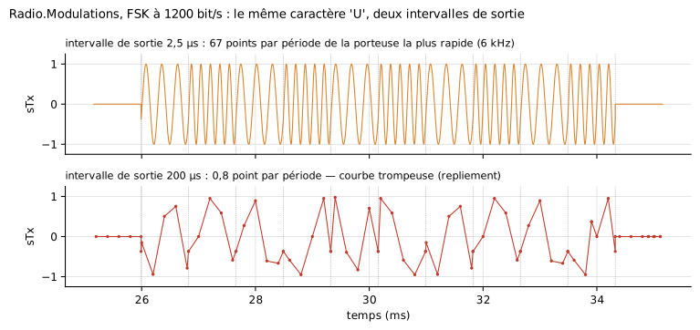
Each module reports it in the log at the start of the simulation, when the output interval exceeds 1/(10 × the fastest carrier): it gives the number of points per period and the interval to choose. To hide this message, when the carrier is not looked at, uncheck warnSampling (Drawn signal tab).
The other curves of the library are not concerned: the edges of a digital output, of a UART or I2C frame, of a PWM are events, written to the result file whatever the output interval.
The price of a short interval: at 2 µs, Radio.Link (0.25 s simulated) writes a result file of about 150 MB and simulates about six times slower than at 100 µs. Simulate a short duration, or keep a long interval when the carrier is not looked at.
Parameters
Serial link (General tab, Serial link (microcontroller side) group)
| Parameter | Default | Role |
|---|---|---|
baudrate |
9600 | Speed of the link with the microcontroller, in baud |
dataBits |
8 | Data bits (5 to 8) |
parity |
None |
Parity: None, Even or Odd |
stopBits |
1 | Stop bits (1 or 2) |
Radio (Radio group)
| Parameter | Default | Role |
|---|---|---|
modulation |
FSK |
OOK, ASK, FSK or BPSK |
fCarrier |
434 MHz | Nominal carrier frequency (the channel) |
channelWidth |
200 kHz | Width of the channel heard around fCarrier |
airBaudrate |
9600 | Air data rate, in bit/s; 8N1 radio frame, independent of the serial link |
halfDuplex |
true |
Deaf while transmitting. With false, the module also hears while it transmits (as if it had two channels) |
Buffers and delays (Buffers and delays group)
| Parameter | Default | Role |
|---|---|---|
txBufferSize |
256 | Transmit buffer (UART to air), in bytes |
rxBufferSize |
256 | Receive buffer (air to UART), in bytes |
txDelay |
5 ms | Minimal fixed delay between the end of a byte on the UART and its radio transmission |
rxDelay |
1 ms | Minimal fixed delay between the end of a radio frame and the transmission of the byte on the UART |
Drawn signal (Drawn signal tab)
Drawn carrier group, illustrated in the parameter dialog by the diagram above; typical values: tables above.
| Parameter | Default | Role |
|---|---|---|
fDisplay |
4 × airBaudrate |
Scaled carrier used to draw sTx: 4 periods per bit (38.4 kHz at 9600 bit/s); the higher it is, the shorter the output interval must be |
deltaFDisplay |
airBaudrate |
FSK: frequency shift of the drawn carrier, 3 and 5 periods per bit for a 0 and a 1 |
askLowAmplitude |
0.3 | ASK: amplitude drawn for a 0 (modulation depth 54 %) |
Simulation group:
| Parameter | Default | Role |
|---|---|---|
warnSampling |
true |
Warns in the log when the output interval is too long to draw the carrier (more than 1/(10 × the fastest carrier)) |
tickPeriod |
0.1 s | Period of the minimal sync point; a safety net |
Setting fDisplay from the air data rate
The default value shown in grey, 4*airBaudrate, is written in the radio module itself, where airBaudrate is a neighbouring parameter. A value entered in the parameter dialog is written in the model that contains the module: the module must be named there, radioA(fDisplay = 16*radioA.airBaudrate). Writing 16*airBaudrate gives the error Variable airBaudrate not found in scope.
The Electrical tab is the one of the serial devices, optional GND and VCC pins included (useGroundPin, useSupplyPin): for the budget of a supply, set IQ to the consumption of the module (an APC220 draws about 25 to 35 mA).
Quantities to plot
| Variable | Content |
|---|---|
radio.sTx |
Modulated signal transmitted (0 outside transmission) |
radio.sRx |
Signal of the other transmitter, as received |
radio.carrierOn |
A radio frame is being transmitted |
radio.airRxBusy |
A radio frame is being received |
radio.txFill, radio.rxFill |
Bytes waiting in the buffers |
radio.nSent, radio.nReceived |
Radio frames transmitted, received intact |
radio.nDropped |
Bytes lost for lack of room in a buffer |
radio.nCorrupted |
Radio frames lost: wrong, jammed, or cut by our own transmission in half duplex |
radio.heard, radio.collision |
One transmitter audible on the channel; two transmitters at once |
At the end of the simulation, each module writes a one-line summary in the log: bytes received from the UART, transmitted, received by radio, delivered to the UART, and bytes lost with their cause. Losses are also reported while the simulation runs (the first ten).
Examples
| Example | What it shows |
|---|---|
Radio.Link |
The PING/PONG programs of MultiMcu.Uart, unchanged, through two radio modules |
Radio.Overflow |
An air data rate eight times slower than the serial link and a 16-byte buffer: the end of the message is lost |
Radio.Modulations |
The same character in OOK, ASK, FSK and BPSK |
Things to try on Radio.Link: set radioB.fCarrier to 440 MHz (B no longer hears anything), or radioB.airBaudrate to 4800 (the frames arrive wrong and are dropped).
Limits
- Masked synchronisation only: the receiver decodes the bit carried by the wire, it does not demodulate the drawn signal (no filter).
- No channel: no distance, attenuation, noise or bit error rate.
- One transmitter at a time on a wire: two simultaneous transmissions jam each other, even when set to different frequencies. Two independent links = two wires.
- The radio frame is one 8N1 frame per byte, with no preamble, packet or checksum: a wrong byte that passes the frame check is delivered.
- Default delays (5 ms and 1 ms) and channel width (200 kHz) assumed, for lack of data in the APC220 datasheet.
- 48 radio modules at most in a model.