The MCU block
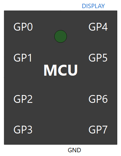
MicroPythonMCU.MCU is the microcontroller: a package with 8 input/output pins, a ground, a link to a teaching display and an on-board LED. Its behaviour is entirely described by the Python program given by scriptPath. Its reference is the Raspberry Pi Pico (RP2040), whose MicroPython API it reproduces (rp2 port); the icon deliberately reads "MCU". Inside, a programmable core (core, an Internal.McuCore component) — the same as in the Raspberry Pi Pico board —, an ideal supply VOH and the on-board LED: the internal diagram (Diagram tab) shows them wired. For a board with its real supply pins and regulator, see RPi_Pico.
Connectors
| Connector | Type | Role |
|---|---|---|
GP0 … GP7 |
Electrical pin (PositivePin) |
Each one, at the program's choice: digital input or output (Pin), analog input (ADC), PWM output (PWM), serial line (UART) or I2C bus line (I2C). GP0-GP3 are on the left edge of the icon, GP4-GP7 on the right edge |
GND |
Electrical pin (NegativePin) |
Common reference of all pins. Connect it to the circuit ground (Ground), as on a real board. Hidden when useGroundPin is unchecked |
Display0 |
Logical link (DisplayLinkOutput) |
To a Peripherals.Display, Display4x32 or Display8x32 (one or several): text sent by machine.Display(0).write(). Not electrical: see LED and displays |
The on-board LED (Pin.LED, pin 25 on the Pico) is wired inside the block, with its series resistor: it has no connector. It lights up on the icon, and its current can be plotted under mcu.builtinLed.
Electrical model of a pin
Each GPx pin is a small circuit made of standard electrical components, solved together with the rest of the diagram. The program only controls it.
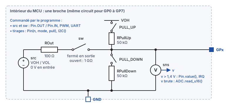
Labels of the diagram, in French: "Intérieur du MCU : une broche" = inside the MCU, one pin (same circuit for GP0 to GP7); "Commandé par le programme" = controlled by the program; "0 V en entrée" = 0 V as an input; "fermé en sortie" = closed as an output; "ouvert" = open; "tirages" = pull resistors; "v brute" = raw voltage.
- Output stage: as an output (
Pin.OUT,PWM,UARTtransmission), the pin is connected through a resistanceROuteither to the supply of the core (VOH: high level) or toVOL(low level). The current delivered by the pin is drawn from the supply — on the Pico, hence from the regulator, and from the battery. The actual pin voltage depends on what is connected: ≈ 3.07 V with an LED and 330 Ω, for instance. - As an input, the output stage is off: the pin is in high impedance. Only a 1 GΩ leakage remains (
GOff): a floating pin ends up at 0 V, and the weakest external resistor is enough to set its level. - Internal pull resistors: two 50 kΩ resistors, one to
VOH(Pin.PULL_UP), the other to ground (Pin.PULL_DOWN), switched on byPin(n, mode, pull). They act whatever the direction.I2C()andI2CTarget()switch on the pull-up of SCL and SDA, as on the Pico;ADC(n)switches off the pulls of its pin. - Reading: a voltage sensor measures the pin at all times, whatever its direction. The program reads 1 above 1.4 V, 0 below: a single threshold,
(VIL + VIH)/2, without hysteresis. TheADCreads the voltage as is, on 16 bits, withVOH(3.3 V) as reference.
The pull resistors are controlled conductances rather than switches: 1/50 kΩ when active, 1 pS otherwise. A pin that the program does not use can be left unconnected. At start-up, no pin has a pull resistor. No open-drain mode yet (Pin.OPEN_DRAIN): see the limitations.
Example: Gpio.Pull, two buttons without any external resistor.
Parameters
Double-clicking the MCU opens its parameter dialog. The defaults suit most uses: only the script path needs setting.
Python script
General tab, "Python script" group.
| Parameter | Default | Role |
|---|---|---|
scriptPath |
Resources/Scripts/MCU/demo.py |
Program to run (pick it with the … button). With a file system enabled, it runs after boot.py, instead of main.py; if empty, the flash's main.py runs |
addScriptDirToPath |
true |
Makes the .py files next to the script importable (import my_module), as on the board, where the flash root is on the import path |
libraryPath |
"" |
Optional: any .py file of a shared library folder. Its folder is added to the import path |
A program is therefore split up as on the board: main.py + modules, or an off-the-shelf driver placed next to the program that imports it (examples Program.Imports, I2c.GroveLcd, Weighing.KitchenScale).
Synchronisation
General tab.
| Parameter | Default | Role |
|---|---|---|
tickPeriod |
0.1 s |
Period of the minimal synchronisation point between the program and the circuit: outputs are read back at least at this rate, even if the program never sleeps. The default is fine |
Execution time
Execution time tab.
| Parameter | Default | Role |
|---|---|---|
gpioOpTime |
5e-6 s |
Duration of a pin access (value(), on(), off(), pin(x)), the order of magnitude of MicroPython on an RP2040. Two successive writes without a sleep thus produce a real 5 µs pulse, which enables bit-banging (HX711 driver). 0 makes accesses instantaneous |
hangWarningTime |
10 s |
Real (wall-clock) time after which a warning in the log reports a program that does not let the simulation advance: a loop without sleep() nor pin access, or a loop of pin accesses with gpioOpTime = 0. Repeated at 20 s, 40 s… The simulation is not interrupted (stop it from OMEdit if needed). 0: never any warning |
Pure Python computation, creating a pin, the ADC, PWM and reading the clock remain instantaneous.
Electrical
Electrical tab. The defaults approximate an RP2040 powered at 3.3 V.
| Parameter | Default | Group | Role |
|---|---|---|---|
VOH |
3.3 V | Logic levels | Ideal internal supply: output voltage in the high state, voltage of the pull-ups and reference of the ADC |
useGroundPin |
true |
Supply | Shows the GND pin. Unchecked: the pin disappears and the microcontroller is referenced to the simulation ground (0 V, common to every Ground block), nothing to wire |
VOL |
0 V | Logic levels | Output voltage in the low state |
VIH |
2.0 V | Logic levels | With VIL, sets the single reading threshold (VIL + VIH)/2 = 1.4 V: above it, an input reads 1 |
VIL |
0.8 V | Logic levels | See VIH: below the threshold, an input reads 0 |
ROut |
100 Ω | Output stages | Series resistance of each output (current the pin can deliver) |
ledSeriesR |
330 Ω | Output stages | Series resistance of the on-board LED |
RPullUp |
50 kΩ | Input stages | Internal pull-up to VOH, switched on by Pin.PULL_UP and by I2C() / I2CTarget() on SCL and SDA |
RPullDown |
50 kΩ | Input stages | Internal pull-down to ground, switched on by Pin.PULL_DOWN |
GOff |
1e-9 S | Input stages | Leakage of a pin that does not drive its line (input, released I2C line), to ground: 1 GΩ |
File system
File system tab, "Simulated flash" group. What the program sees: API, file system.
| Parameter | Default | Role |
|---|---|---|
fsEnabled |
false |
Enables the simulated flash. When disabled, open() and os raise OSError |
fsSource |
"" |
Initial flash image: a folder (data, boot.py, main.py, lib/), given by any of its files, by its path or by a modelica:// URI. Empty: blank flash |
fsWorkspace |
"." |
Folder where each simulation creates its copy of the flash, named <instance>_<FS name>_<date>_<time> (blank for a blank flash). Relative to the simulation folder |
fsOpenExplorer |
true |
Opens Windows Explorer on the copy at the end of the simulation |
The source image is never modified: each simulation starts from a fresh copy, whose path is shown in the log. To chain two simulations, use the copy left by the previous one as fsSource. Example image supplied: Resources/FileSystems/datalogger/ (examples FileSystem.Boot and FileSystem.Script).
Debugging
Debugging tab. Details and walkthrough in Debugging with VS Code.
| Parameter | Default | Role |
|---|---|---|
debugEnabled |
false |
Step-by-step debugging with VS Code: at start-up, the microcontroller waits until VS Code attaches (the simulation stays at t = 0), then the program can be paused, stepped line by line and inspected. During a pause, simulated time is frozen. One MCU per model |
debugPort |
5678 |
Local port the debugger (debugpy) listens on: the one in the VS Code attach configuration |
Variables to plot
| Variable | Contents |
|---|---|
mcu.GP0.v … mcu.GP7.v |
Voltage of each pin: the signal as an oscilloscope would see it (serial frames, PWM and I2C bus included) |
mcu.GP0.i … |
Current flowing into the pin |
mcu.builtinLed.… |
On-board LED |
mcu.Display0.seq |
Number of messages sent to the display |
Several microcontrollers in a model
A model can hold as many MCU blocks as needed, wired together like real boards: pin to pin (GP of one to GP of the other), through a crossed serial link, or on a shared I2C bus where one is the controller (machine.I2C) and the other a target (machine.I2CTarget). A common ground is still required.
Each microcontroller runs its own program, isolated from the others: its variables, its imported modules (a driver imported by two boards is loaded twice), machine, time and its file system (each one gets its own copy of the flash, even when they start from the same fsSource image). Two boards can therefore run the same file without interfering.
As soon as there are two microcontrollers, every line printed by their print() carries, after the simulated time, the instance name in the simulation log ([t=0.500030 s] [MyModel.mcuA] ...), as Python-programmable peripherals already do. With a single MCU, only the time precedes the line.
Examples: Several microcontrollers.