Serial devices (UART)
On the program side, machine.UART produces a real electrical frame on two microcontroller pins (API). At the other end of the wire, Peripherals provides five serial devices: they decode what they receive, bit by bit, and reply with a real frame in turn.
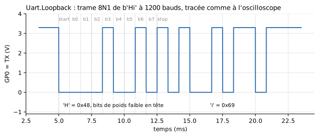
Voltage of the transmit pin (mcu.GP0.v) in the Uart.Loopback example: start bit at 0, 8 data bits (least significant first), stop bit at 1. Figure labels are in French: « temps » = time, « bits de poids faible en tête » = least significant bits first.
Wiring
Two crossed wires and a common ground, as on a real board:
| Microcontroller | Device | Direction |
|---|---|---|
TX pin chosen by the program (e.g. GP5) |
RX |
what the microcontroller sends |
RX pin chosen by the program (e.g. GP4) |
TX |
what the device replies |
GND |
GND |
common reference, required |
from machine import Pin, UART
import time

uart = UART(0, baudrate=1200, tx=Pin(5), rx=Pin(4))
uart.write(b'AT+TEMP\n')
time.sleep_ms(200)              # give the reply time to arrive
if uart.any():
    print(uart.readline())      # b'TEMP=21.5\r\n'
Reception does not wake the program up: it polls the link with any(), read() or readline().
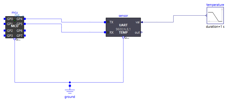
Why GP4/GP5 in the examples?
These pins are on the right edge of the MCU icon, on the side where the device is placed: wires stay short. Any pair of GP0-GP7 works.
Supplied devices
They all share the same connectors and parameters; they only differ by their defaults and their icon. The only exception, UartLcd20x2 shows only the frame format (baudrate, dataBits, parity, stopBits) and the Electrical tab: its other settings are fixed, and it has neither a TX pin nor a valueOut connector (it transmits nothing and returns nothing to the model).
| Component | What it does | Defaults that set it apart |
|---|---|---|
UartGenericDevice |
Device to be configured entirely in its parameter dialog | respondEnabled = true, empty table |
UartEchoDevice |
Sends back each received byte as is | echoEnabled = true |
UartTemperatureSensor |
Answers AT+TEMP with the value of its input, AT+ID with its identifier, and accepts a setpoint through SET <number> |
commandTable = "AT+TEMP=>TEMP={v1:.1f}\r\n|AT+ID=>SIM-TEMP-1\r\n|SET {o1}=>OK\r\n", responseDelay = 5 ms, useValueInput = true, fixedValue = 20, nOut = 1 |
UartGpsModule |
Sends a position frame every second on its own, without being asked | periodicEnabled = true, periodicTemplate = "$GPGLL,{v1:.4f},{v2:.4f},{v3:.1f}\r\n", useValueInput = true, nIn = 3 |
UartLcd20x2 |
2 × 20 character display: shows each received line on its icon, the previous one moving down to line 2 | never replies: no TX pin nor valueOut connector; only baudrate, dataBits, parity, stopBits and the Electrical tab can be set, the rest is fixed (final): empty command table, end of line \n, neither echo nor transmission |

Connectors
On the program side, the link is written with machine.UART: see the API and the official MicroPython documentation (machine.UART, rp2 port).
| Connector | Role |
|---|---|
TX |
Device transmit, to the microcontroller's RX pin. Present when useTxPin is checked (default) |
RX |
Device receive, from the microcontroller's TX pin |
GND |
Ground, to connect to the microcontroller's, only when useGroundPin is checked (default) |
VCC |
Supply of the device, only when useSupplyPin is checked (bottom left of the icon): for instance 3V3(OUT) of a Raspberry Pi Pico |
valueIn[nIn] |
Model quantities the device inserts into its frames ({v1}…): a temperature, a position… Used if useValueInput = true |
valueOut[nOut] |
Quantities extracted from received frames ({o1}…): the device then becomes an actuator. May stay unconnected. Present when useValueOutput is checked (default) |
Frame format
The device uses its own format, set by dataBits, parity and stopBits (8N1 by default) and shown on its icon (1200,N,8,1, 1200,E,8,2…). It must be the one the program passes to UART(...):
uart = UART(0, baudrate=1200, bits=8, parity=0, stop=2, tx=Pin(5), rx=Pin(4)) # device: parity = Even, stopBits = 2
On a mismatch, the device and the microcontroller keep the bytes received with an error but report them in the log (parity error, framing error; the first ten, then a total at the end of the simulation). A parity mismatch lets correct bytes through, merely reported; a baud rate or data-bit mismatch gives wrong bytes. The Uart.Format and Uart.FormatMismatch examples show both situations.
Parameters
Behaviour and link (General tab)
| Parameter | Default | Role |
|---|---|---|
behaviour |
Table |
Where the behaviour comes from: Table (command table, below) or Script (Python file) |
scriptPath |
the device's script | .py file describing the behaviour, in Script mode. Each supplied device has its own in Resources/Scripts/Device/ (generic.py, echo.py, temperature_sensor.py, gps.py), equivalent to its table |
baudrate |
1200 | Device baud rate. It must match the microcontroller's, otherwise received bytes are wrong, as on a real board |
dataBits |
8 | Number of data bits of a frame, from 5 to 8 (bits= of machine.UART) |
parity |
None |
Parity: None, Even (parity=0 in the program) or Odd (parity=1) |
stopBits |
1 | Number of stop bits, 1 or 2 (stop= of machine.UART) |
terminator |
"\n" |
Character ending a received command (only the first character counts) |
tickPeriod |
0.1 s | Period of the minimal synchronisation point; a safety net, the default is fine |
Command table (Table tab, Table mode)
| Parameter | Default | Group | Role |
|---|---|---|---|
respondEnabled |
true |
Request / response | Answer the commands recognised by the table |
commandTable |
"" |
Request / response | Table "CMD=>REPLY|CMD=>REPLY" (format below) |
responseDelay |
2 ms | Request / response | Delay between the end of the received command and the start of the reply. Also used in Script mode |
echoEnabled |
false |
Request / response | Send back each received byte as is, as soon as it is decoded |
periodicEnabled |
false |
Periodic transmission | Send spontaneously, without being asked |
period |
1 s | Periodic transmission | Period of spontaneous sending (in Script mode: period of on_tick calls) |
periodicTemplate |
"" |
Periodic transmission | Frame sent periodically |
Inputs / outputs (Inputs / outputs tab)
| Parameter | Default | Role |
|---|---|---|
useValueInput |
false |
Take the quantities from the valueIn connector; otherwise, fixedValue |
nIn |
1 | Number of quantities received from the model (4 at most) |
fixedValue |
0 | Value used when valueIn is not used |
useValueOutput |
true |
Shows the valueOut connector. Unchecked: the device returns nothing to the model |
nOut |
1 | Number of quantities returned to the model on valueOut (4 at most) |
valueOutStart |
0 | Value of valueOut before any capture |
Electrical (Electrical tab)
| Parameter | Default | Role |
|---|---|---|
useGroundPin |
true |
Shows the GND pin. Unchecked: the pin disappears and the device is referenced to the simulation ground (0 V, common to every Ground block), nothing to wire |
useTxPin |
true |
Shows the TX pin. Unchecked, for a device that never transmits: the pin disappears, the output stage stays unconnected |
useSupplyPin |
false |
Shows the VCC pin: the device is then supplied by the circuit, its high levels follow VCC and it draws its quiescent current IQ from it. Unchecked: ideal internal supply VOH, nothing to wire |
VOH |
3.3 V | Ideal internal supply (without VCC): high level of the outputs and of the pull-ups |
IQ |
1 mA | Quiescent current drawn from VCC (with useSupplyPin) |
VOL |
0 V | Low level sent on TX (the high level is the supply: VOH or VCC) |
VIH, VIL |
2.0 V, 0.8 V | Reading thresholds of RX |
ROut |
100 Ω | Series resistance of the TX output |
RPullUp |
1 MΩ | RX pull-up to the supply: an unconnected input reads an idle level |
Describing the device with a table
A single string describes all commands: "CMD=>REPLY|CMD=>REPLY". The characters | and => are reserved. A command is recognised when the complete received line (without its terminator) is identical to it.
| Marker | Where | Meaning |
|---|---|---|
{v1}, {v2:.3f} |
in a reply or in periodicTemplate |
inserts valueIn[N], with an optional Python format |
{o1}, {o2} |
in a command | captures the number received at that place into valueOut[N] |
With this table, the program reads the temperature over the serial link and sends back a command over the same link. valueOut[1] passes it to the rest of the model: this is what the Uart.Regulation example does, a complete control loop through the two wires of the link alone.
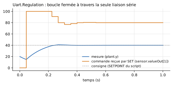
Legend: « mesure » = measurement, « commande reçue par SET » = command received through SET, « consigne » = setpoint.
Describing the device with a Python script
With behaviour = Script, the scriptPath file replaces the table. It defines up to three functions, all optional:
state = 'STOPPED'       # module variables: the device state,
readings = 0            # which persists from one call to the next

def on_receive(line, t, v):         # once per complete received line
    global state, readings
    if line == b'START':
        state = 'RUNNING'
        return b'OK\r\n'
    if line == b'READ' and state == 'RUNNING':
        readings += 1
        return 'VAL=%.2f N=%d\r\n' % (v[0], readings)
    return b'ERR\r\n'

def on_tick(t, v):                  # every `period` seconds, if defined
    return None

def outputs():                      # read after each call -> valueOut
    return (1.0 if state == 'RUNNING' else 0.0, readings)
| Function | Called | Receives | Returns |
|---|---|---|---|
on_receive(line, t, v) |
once per received line | line: bytes without the terminator; t: simulated time (s); v: tuple of the valueIn quantities |
bytes, str or None: reply sent after responseDelay |
on_tick(t, v) |
every period seconds; its mere presence enables periodic sending |
same | same, sent right away |
outputs() |
after each of the other two, and at load time | — | a number or a sequence, copied to valueOut |
Rules to know:
- The script is loaded once per device: two devices using the same file each have their own variables.
- Each line is delivered only once, even if the simulation re-evaluates the same instant several times: a state machine never replays its transitions.
- Functions must return without waiting: no
sleep()(responseDelaydelays a reply), nomachinenortime, which belong to the microcontroller. The file must be self-contained (no import of neighbouring files). print()goes to the log, prefixed with the device name. An exception stops the simulation.
Starting point: copy Resources/Scripts/Device/generic.py. Examples: Uart.EchoPy, Uart.GpsPy, Uart.StateMachinePy.
Variables to plot
| Variable | Contents |
|---|---|
dev.TX.v, dev.RX.v |
Voltages of both lines (for a device named dev) |
dev.txActive |
A frame is being sent |
dev.rxBusy |
A frame is being received |
dev.valueOut[N] |
Quantities captured by {oN} or returned by outputs() |
Looping the link back onto the microcontroller
To watch the frame of an MCU alone, without a device, connect its TX pin to its RX pin. Not with a plain wire: a direct connect() between two pins of the same MCU makes the driven voltage disappear from the results. Go through a 1 kΩ resistor, with a 1 nF capacitor from the RX pin to ground, as in the Uart.Loopback example; the frame is not distorted (time constant ≈ 1 µs, for 833 µs bits at 1200 baud).
Examples
| Example | What it shows |
|---|---|
Uart.Loopback |
Frame looped back onto the microcontroller, readable as on an oscilloscope |
Uart.EchoPy, Uart.Echo |
Dialogue with an echo device, in Script then Table mode |
Uart.Sensor |
Querying a temperature sensor, then sending a setpoint |
Uart.Regulation |
Closed control loop through the serial link |
Uart.GpsPy |
Spontaneous frames from a GPS module, counted by the program |
Uart.StateMachinePy |
State-machine device described in Python |
Uart.Lcd |
20x2 serial display; changing its baudrate shows the wrong characters of a mismatched baud rate |