machine / time API
This page lists what a program run by the MCU can call: the subset of the Raspberry Pi Pico's MicroPython machine/time API that is actually implemented. For the details of each class, see the official MicroPython documentation — in particular the quick reference of the rp2 port (Raspberry Pi Pico): each section below links to it and only describes what is simulated and what differs. The same API applies to the RPi_Pico board, with the differences of the real board noted below ("On the Pico"). A program written for the board runs unchanged as long as it sticks to this subset. The exact implementation (source of truth) is the file MicroPythonMCU/Resources/Scripts/_shim/machine_time_shim.py, loaded and run as is before the user script. How these modules are built is described in the (French) maintainer reference: Python integration and Life cycle.
Key notion: a call that synchronises hands control back to Modelica (the solver may advance simulated time, possibly up to a pending sleep) before the script continues — this is what makes an input transition or a sleep visible, and compressible, in the simulation. A call that does not synchronise is a plain immediate read of state the script already knows.
Time cost of pin accesses: each value(), on(), off() or pin(x) keeps the processor busy for MCU.gpioOpTime of simulated time (Execution time tab, 5 µs by default, the order of magnitude of MicroPython on an RP2040). Two writes without a sleep in between therefore produce a real pulse, visible to the circuit: this is what enables bit-banging (HX711 driver, see Weighing chain), and what makes time advance in a busy-wait loop (while not button(): pass). Pure Python computation, Pin(), irq(), the ADC, PWM and ticks_* remain instantaneous. gpioOpTime = 0 makes all accesses instantaneous.
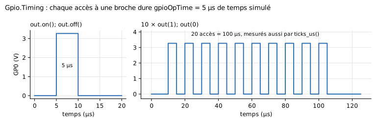
Gpio.Timing: each pin access lasts gpioOpTime = 5 µs of simulated time. Figure labels are in French: « temps » = time, « 20 accès = 100 µs, mesurés aussi par ticks_us() » = 20 accesses = 100 µs, also measured by ticks_us().
machine.Pin
Official MicroPython documentation: machine.Pin · rp2 port: quick reference
Constants
| Constant | Value | Use |
|---|---|---|
Pin.IN |
0 |
input mode, passed to mode= |
Pin.OUT |
1 |
output mode, passed to mode= |
Pin.PULL_UP |
1 |
passed to pull=: switches on the internal pull-up to VOH (MCU.RPullUp, 50 kΩ) |
Pin.PULL_DOWN |
2 |
passed to pull=: switches on the internal pull-down to ground (MCU.RPullDown, 50 kΩ) |
Pin.LED |
25 |
identifier of the on-board LED (wired inside the MCU, not a GPx connector) |
Constructor
Pin(id, mode=None, pull=None)
id:0-7(pinsGP0-GP7), or25/Pin.LED/"LED"(on-board LED). Any other value raisesValueErrorat the first call that uses it.mode:Pin.INorPin.OUT. If omitted, the direction is not (re)configured — handy to just read the current state.pull:Pin.PULL_UP,Pin.PULL_DOWNorNone. Electrically real: see the electrical model of a pin.
As on the rp2 port, Pin(n) alone changes nothing; as soon as mode or pull is given, the constructor calls init(mode, pull), which always rewrites the pull: Pin(n, Pin.IN) switches off a pull set before. Synchronises in that case.
Methods
| Method | Signature | Behaviour | Synchronises? |
|---|---|---|---|
.value() |
value() -> int |
Waits gpioOpTime, then reads the resolved pin state (0/1) at the end of the access, whatever its direction |
Yes |
.value(x) |
value(x) |
Drives the pin to x (0/1) right away — no effect if the pin is currently an input —, then waits gpioOpTime |
Yes |
pin() / pin(x) |
__call__(x=None) |
Shorthand for value() / value(x), common in MicroPython drivers |
Yes |
.init(mode, pull) |
init(mode=None, pull=None) |
Reconfigures the pin: direction if mode is given, pull always (None switches it off) |
Yes |
.on() |
on() |
Same as value(1) |
Yes |
.off() |
off() |
Same as value(0) |
Yes |
.high() / .low() |
high() / low() |
Same as on() / off() (aliases specific to the rp2 port) |
Yes |
.toggle() |
toggle() |
Inverts the current state (reads, then writes the opposite) | Yes (through value(), twice) |
.irq(handler, trigger) |
irq(handler=None, trigger=IRQ_RISING|IRQ_FALLING, **kwargs) |
Registers (or clears, if handler=None) a callback called on an edge matching trigger. The callback receives the Pin object (handler(pin)), as on real MicroPython. **kwargs absorbs hard=/priority=/wake= for signature compatibility, with no effect (see Limitations) |
Yes |
trigger constants: Pin.IRQ_RISING = 1, Pin.IRQ_FALLING = 2 (combine with | for both edges; always use the symbolic names). The callback runs "soft": it is executed at the next wake-up point of the program, never as an immediate pre-emption of the script. An input transition wakes the script up even without a registered irq(); registering an irq() adds the callback call to that wake-up, and a pending sleep() still returns early.
machine.ADC
Official MicroPython documentation: machine.ADC · rp2 port: quick reference
Constructor
ADC(id) — id: 0-7 (any of the GP0-GP7 pins, used as analog rather than digital — all of them are ADC-capable here, unlike the real Pico where only GP26-GP28 are) or a Pin object (its .id is used). The on-board LED is not ADC-capable. Synchronises. Changes neither the direction nor the driven state of the pin, but disconnects its digital input, as on the RP2040: logic-threshold crossings of the analog voltage no longer wake a pending sleep() nor trigger IRQs. A later Pin(id, mode) gives the pin back to the GPIO.
On the Pico: as on the rp2 port, id is a channel 0-4 — ADC(0)-ADC(2) = GP26-GP28, ADC(3) = VSYS/3, ADC(4) (ADC.CORE_TEMP) = temperature sensor — or a pin GP26-GP29; elsewhere, ValueError: Pin doesn't have ADC capabilities.
Methods
| Method | Signature | Behaviour | Synchronises? |
|---|---|---|---|
.read_u16() |
read_u16() -> int |
Reads the voltage on the pin and returns it on 16 bits (round(v / Vref * 65535), clamped to [0, 65535]; Vref = VOH for MCU, ADC_VREF for the Pico) |
Yes |
machine.PWM
Official MicroPython documentation: machine.PWM · rp2 port: quick reference
from machine import Pin, PWM
pwm = PWM(Pin(0))
pwm.freq(1000)          # Hz
pwm.duty_u16(32768)     # 0-65535 (~50%)
Once configured, the square wave is generated continuously on the Modelica side, without a round trip to the Python program at each edge — the script may end, PWM keeps running, as the RP2040 hardware peripheral does.
Constructor
PWM(pin, freq=None, duty_u16=None) — pin: 0-7 (integer) or Pin object. Makes the pin an output (as on the real RP2040). freq/duty_u16 are optional, equivalent to calling .freq()/.duty_u16() right after construction.
Methods
| Method | Signature | Behaviour | Synchronises? |
|---|---|---|---|
.freq(f) |
freq(f) |
Sets the PWM frequency (Hz); also makes the pin an output | Yes |
.freq() |
freq() -> int |
Returns the last frequency set (cached value) | No |
.duty_u16(d) |
duty_u16(d) |
Sets the duty cycle (0-65535, clamped) | Yes |
.duty_u16() |
duty_u16() -> int |
Returns the last duty cycle set (cached value) | No |
.deinit() |
deinit() |
Stops PWM; the pin goes back to a plain digital output (low by default) | Yes |
machine.Timer
Official MicroPython documentation: machine.Timer · rp2 port: quick reference
from machine import Timer
tim = Timer(period=500, mode=Timer.PERIODIC, callback=lambda t: led.toggle())
# or in two steps: tim = Timer() then tim.init(period=500, ...)
tim.deinit()
Software timer: once armed, the callback keeps firing during a sleep() pending elsewhere in the script, without ever making it return early.
Constants
| Constant | Value | Use |
|---|---|---|
Timer.ONE_SHOT |
0 |
the callback fires once, then the timer disarms itself |
Timer.PERIODIC |
1 |
the callback fires again every period ms, indefinitely |
Constructor
Timer(id=-1, **kwargs) — id accepted for signature compatibility, ignored (a fixed pool of 4 software timers is shared by all Timer()s, see Limitations). Without any other argument, does not synchronise. As in MicroPython, the keyword arguments of init() given to the constructor start the timer at once: Timer(period=500, mode=Timer.PERIODIC, callback=f) is the same as Timer() followed by init(period=500, mode=Timer.PERIODIC, callback=f).
Methods
| Method | Signature | Behaviour | Synchronises? |
|---|---|---|---|
.init(period, mode, callback, freq) |
init(period=1000, mode=PERIODIC, callback=None, freq=None) |
Arms (or re-arms) the timer: period in milliseconds (as in real MicroPython), or freq in hertz instead (freq=10 is the same as period=100), mode = ONE_SHOT/PERIODIC, callback receives the Timer object (callback(timer)) |
Yes |
.deinit() |
deinit() |
Stops and frees the timer | Yes |
machine.Display
Specific to this library: machine.Display does not exist in MicroPython (teaching tool, see LED and displays).
from machine import Display
display = Display(0)
display.write("Hello")          # to a Peripherals.Display wired to MCU.Display0
display.write("T =", 21.5, "C") # like print(): "T = 21.5 C"
Single, write-only logical link to a teaching display (Display0 on the MCU). Not a real UART/serial protocol: no reception, no addressing. Unlike the GPx pins, the link is not electrical: the message is delivered instantly at the next synchronisation point, with no simulated baud rate nor bit-level waveform — component and wiring: LED and displays.
Constructor
Display(id=0, **kwargs) — id: only 0 is supported (ValueError at construction otherwise). **kwargs accepted, with no effect. Does not synchronise.
Methods
| Method | Signature | Behaviour | Synchronises? |
|---|---|---|---|
.write(*args, sep, end) |
write(*args, sep=' ', end='\n') |
Used like print(): the arguments are converted by str(), joined by sep and followed by end. Each line feed sends the line before it, which becomes one message for the display wired to MCU.Display0 (one line of the screen); instant delivery of the whole message. A text without a final line feed (end='') waits for the rest from a later call |
Yes, at each message sent |
Examples:
display.write("Hello")                # one message: "Hello"
display.write("T =", 25, "C")         # "T = 25 C"
display.write("a", "b", sep="-")      # "a-b"
display.write("T =", end="")          # nothing sent yet...
display.write(25)                     # ... then "T =25"
display.write("Line 1\nLine 2")       # two messages, two lines of the screen
Several messages written without sleep() in between (or a text of several lines) arrive at the same simulated instant: the display receives all of them, in order, as if they had been sent one by one. A message written before the first sleep() of the program (at t = 0) is shown as well.
machine.UART
Official MicroPython documentation: machine.UART · rp2 port: quick reference
from machine import Pin, UART
uart = UART(0, baudrate=1200, tx=Pin(0), rx=Pin(1))
uart.write(b'Hi')
if uart.any():
    print(uart.read())
Electrically real serial link, on two real GPx pins — unlike machine.Display, which is a logical link. The TX pin carries a real frame (start bit at 0, data bits least significant first, optional parity bit, stop bits at 1, idle high; 8N1 by default), each bit lasting 1/baudrate: plotting it in OMEdit is like looking at it on an oscilloscope.
The waveform is produced by the runtime, without the Python program driving each edge — like the RP2040 hardware UART, which runs on its own once programmed. Reception is decoded from the line's edges, reading each bit in its middle as a real receiver does.
A pin assigned to UART reception no longer generates GPIO interrupts and no longer wakes a pending sleep(): its edges belong to the serial peripheral, not to the script — as on real hardware.
Wiring and devices to connect at the other end: Serial devices.
Constructor
UART(id=0, baudrate=1200, bits=8, parity=None, stop=1, tx=None, rx=None, **kwargs) — id: only 0 is supported. tx/rx: required, a Pin object or a pin number, two distinct pins among 0-7. baudrate: 50 to 115200. Frame format, as on the rp2 port: bits from 5 to 8 (with fewer than 8 bits, the most significant bits of the byte are lost), parity None, 0 (even) or 1 (odd), stop 1 or 2; any other value raises ValueError. The other arguments of the port (timeout, txbuf, rxbuf, flow…) are accepted with no effect. .init(...) takes the same arguments and reconfigures the link. Synchronises.
Byte received with an error. A byte whose parity bit is wrong, or whose stop bit is low (baud rate or format different from the transmitter's), is kept in the receive queue, as on the RP2040; the simulation log shows a timestamped warning (parity error, framing error) for the first ten, then the total at the end of the simulation. The receiver only checks the first stop bit.
Methods
| Method | Signature | Behaviour | Synchronises? |
|---|---|---|---|
.write(data) |
bytes, str (UTF-8 encoded) or any convertible object |
Queues the bytes for sending and returns the number accepted. Non-blocking: the script continues while Modelica plays the waveform; frames follow each other with no gap. 256-byte queue; extra bytes are silently lost | Yes |
.any() |
— | Number of received bytes waiting to be read | Yes |
.read(n=None) |
n bytes, or everything available |
Returns bytes, or None if nothing is available |
Yes |
.readline() |
— | Reads up to and including \n; otherwise returns what is available, or None if nothing |
Yes |
.init(baudrate, tx, rx) |
same as constructor | Reconfigures the link | Yes |
.deinit() |
— | Releases the link and its pins | Yes |
machine.I2C
Official MicroPython documentation: machine.I2C · rp2 port: quick reference, software I2C
from machine import Pin, I2C
i2c = I2C(0, scl=Pin(4), sda=Pin(5), freq=100000)   # or I2C(scl=Pin(4), sda=Pin(5))
print(i2c.scan())                                   # e.g. [66]
i2c.writeto(0x42, b'Hello')
print(i2c.readfrom(0x42, 5))
print(i2c.readfrom_mem(0x42, 0x10, 2))              # register 0x10, after a repeated START
Electrically real, open-drain I2C bus on two GPx pins: the microcontroller is the master, it generates the clock and only pulls SDA/SCL low or releases them. The lines only go back up thanks to pull-up resistors. I2C() switches on the internal pull-ups of SCL and SDA (50 kΩ), as the rp2 port does, but they are far too weak for a real bus: the pull-up resistors carried by a peripheral are needed (usePullUp = true). Without them, a released line rises too slowly and every transaction raises OSError(ETIMEDOUT). Wiring and components: I2C devices.
Each transaction is blocking: the script resumes only at the real end of the sequence on the bus, in simulated time (about 9 bits per byte, at 1/freq per bit). Both pins are reserved: their edges do not generate GPIO interrupts and do not wake a sleep().
Constructor
I2C(id=0, *, scl, sda, freq=400000) — id optional (a single bus exists: 0, or 1 accepted as an alias), which makes both the rp2 form I2C(0, scl=..., sda=...) and the form of drivers written for other ports, I2C(scl=..., sda=...), work. scl/sda: required, a Pin object or a number, two distinct pins among 0-7. freq: 1 kHz to 1 MHz (ValueError outside). SoftI2C(scl, sda, *, freq=400000), without identifier, uses the same controller. Synchronises. On the Pico: the pins follow the RP2040 multiplexing (I2C(0): SCL on GP1, 5, 9…, SDA on GP0, 4, 8…; I2C(1): SCL GP3, 7, 11…, SDA GP2, 6, 10…), with the default pins of the rp2 port when missing (I2C(0): SCL GP5/SDA GP4, I2C(1): SCL GP7/SDA GP6); without identifier, that of the chosen pins; I2C(0) and I2C(1), one at a time. SoftI2C accepts any pins. Same rule for UART(0) (TX GP0, 12, 16, 28; default GP0/GP1) and UART(1) (TX GP4, 8, 20, 24; default GP4/GP5): tx/rx become optional.
Methods
| Method | Behaviour | Synchronises? |
|---|---|---|
.scan() |
List of the addresses (0x08-0x77) that acknowledge a probe (empty write); [] if the bus is stuck |
Yes (one transaction per address) |
.writeto(addr, buf, stop=True) |
Writes buf; returns the number of acknowledged bytes. stop=False keeps the bus: the next transaction starts with a repeated START |
Yes, blocking |
.readfrom(addr, nbytes, stop=True) |
Reads nbytes bytes (bytes) |
Yes, blocking |
.readfrom_into(addr, buf, stop=True) |
Same, into an existing buffer | Yes, blocking |
.writevto(addr, vector, stop=True) |
Writes the concatenation of the buffers of vector |
Yes, blocking |
.writeto_mem(addr, memaddr, buf, *, addrsize=8) |
Writes buf starting at register memaddr |
Yes, blocking |
.readfrom_mem(addr, memaddr, nbytes, *, addrsize=8) |
Writes the register number, then reads after a repeated START | Yes, blocking |
.readfrom_mem_into(addr, memaddr, buf, *, addrsize=8) |
Same, into an existing buffer | Yes, blocking |
.init(scl=, sda=, freq=) / .deinit() |
Reconfigures / releases the bus and its pins | Yes |
Errors: OSError(EIO) (errno 5) if the address is not acknowledged; OSError(ETIMEDOUT) (errno 110) if a line stays low (no external pull-up, stuck bus); OSError(EBUSY) (errno 16) for a call from a Timer/IRQ callback during a transaction.
machine.I2CTarget
Official MicroPython documentation: machine.I2CTarget
from machine import Pin, I2CTarget
mem = bytearray(8)
target = I2CTarget(0, 0x42, mem=mem, scl=Pin(4), sda=Pin(5))   # the controller reads and writes mem
mem[0] = 123                                                    # seen by the controller at its next read
Here the microcontroller is an I2C target (slave), on the same open-drain electrical bus as machine.I2C: it never generates the clock, it answers the controller — typically another MCU of the model (see Several microcontrollers). The bus always needs pull-up resistors. As for the controller, both pins are reserved.
Two ways to answer:
- Memory mode (
mem=abytearray): the target behaves as a small memory, with no handler at all. The first bytes written by the controller (mem_addrsizebits) select the address, the following ones are written there, a read sends the memory from that address on; the address moves on at each byte and wraps around at the end of the buffer. This is thewriteto_mem/readfrom_memform on the controller side. The program only keepsmemup to date; the memory keeps answering even after the program has ended. - Interrupt handler (no
mem=): received bytes pile up and are read withreadinto(), bytes to send are queued withwrite(), typically from anirq()handler.
def on_i2c(t):
    flags = t.irq().flags()
    if flags & I2CTarget.IRQ_END_WRITE:      # the controller has finished writing
        n = t.readinto(command)
    if flags & I2CTarget.IRQ_READ_REQ:       # the controller wants to read and nothing is queued
        t.write(reply)

target = I2CTarget(0, 0x43, scl=Pin(4), sda=Pin(5))
target.irq(on_i2c, trigger=I2CTarget.IRQ_END_WRITE | I2CTarget.IRQ_READ_REQ, hard=True)
The handler runs at the same simulated instant as the event, hard or not: for IRQ_READ_REQ, the byte given to write() leaves at once, without the clock stretching a real circuit might need.
Constructor
I2CTarget(id=0, addr, *, addrsize=7, mem=None, mem_addrsize=8, scl, sda) — id: 0 (one target per microcontroller). addr: 7-bit address (addrsize=10 is rejected). mem: a non-empty bytearray (or writable buffer), or None. mem_addrsize: 0, 8, 16, 24 or 32 bits. scl/sda: mandatory, a Pin or a number, two distinct pins among 0-7, other than those of an I2C controller. Synchronises.
Methods and constants
| Method | Behaviour | Synchronises? |
|---|---|---|
.readinto(buf) |
Copies into buf the bytes received from the controller (no-memory mode), returns their number |
No |
.write(buf) |
Queues bytes for the next reads of the controller, returns the number accepted (256-byte queue) | No |
.irq(handler=None, trigger=IRQ_END_READ \| IRQ_END_WRITE, hard=False) |
Registers the handler (called with the target); with no argument, only returns the IRQ object | No |
.irq().flags() |
Events handed to the last call of the handler | No |
.memaddr |
Current memory address (memory mode) | No |
.deinit() |
Releases the target and its pins | Yes |
Event constants: IRQ_ADDR_MATCH_READ, IRQ_ADDR_MATCH_WRITE (address recognised), IRQ_READ_REQ (the controller asks for a byte and the queue is empty), IRQ_WRITE_REQ (a byte has just been received), IRQ_END_READ, IRQ_END_WRITE (end of the read or of the write; in memory mode, no IRQ_END_WRITE for a write that only selected the address).
File system: open() and os
Official MicroPython documentation: os, file systems
import os

with open('/data/measures.csv', 'a') as f:
    f.write('%d;%.3f\n' % (t, u))
print(os.listdir('/data'))
Active only if MCU.fsEnabled is ticked (File system tab, see MCU parameters). Each simulation copies MCU.fsSource (empty = blank flash) into a new <instance>_<FS name>_<date>_<time> folder of the MCU.fsWorkspace workspace ("." by default: the simulation folder), whose path is shown in the log at the start and end of the simulation; Windows Explorer opens on it at the end (MCU.fsOpenExplorer); the script sees this copy as the flash root /, without being able to leave it (.. stops at the root). Without a file system, open() and the os functions raise OSError(ENODEV) (errno 19). The root and /lib are on the import path. Program run: boot.py of the copy if it exists, then MCU.scriptPath instead of main.py, or the copy's main.py if scriptPath is empty.
| Call | Effect | Synchronisation point? |
|---|---|---|
open(path, mode='r') |
File on the flash. Text in UTF-8, line endings never translated | No (instant write) |
os.listdir(dir='.') / os.ilistdir(dir='.') |
Sorted names / tuples (name, type, 0, size), type 0x4000 (folder) or 0x8000 (file) |
No |
os.mkdir(path) / os.rmdir(path) / os.remove(path) |
Creates a folder / removes an empty folder / removes a file | No |
os.rename(old, new) |
Renames, replacing an existing target | No |
os.stat(path) |
10-tuple: [0] type, [6] size; dates at 0 |
No |
os.statvfs('/') |
1.4 MB flash in 4 KB blocks, free blocks computed from the contents | No |
os.chdir(dir) / os.getcwd() |
Current folder (/ at start-up) |
No |
os.sync(), os.uname(), os.sep |
No effect / rp2 identity / '/' |
No |
import uos gives the same module. Errors: those of MicroPython (OSError: [Errno 2] ENOENT, EEXIST, EISDIR...), never the real host path; EINVAL for a path containing \, : or a character forbidden by Windows. Nothing the script observes depends on the copy's timestamp: two simulations produce the same files.
Modules, print() and errors
import my_module               # my_module.py placed next to the program
import sensors                 # /lib/sensors.py on the flash, or folder given by libraryPath
- Imports: the program's folder is on the import path (
MCU.addScriptDirToPath, on by default), like the flash root on the board.MCU.libraryPathadds a shared library folder. With a file system enabled, the flash root and/libare on it too. The CPython 3.12 standard library is available, but a program meant for the board must stick to what MicroPython offers. print(): shown in OMEdit's simulation output window, each line preceded by the simulated time at which it was written, to the microsecond:[t=0.250000 s] value = 12. What goes tosys.stderr(including the traceback of an exception) is shown as a warning, flagged differently by OMEdit.- Uncaught exception: stops the simulation; the Python traceback is shown in the log, with the file path, the line number and the offending line of code (
Program.Errorexample). Forboot.py/main.py, the path is the one of the file in the copy of the flash. sys.exit(): ends the program without error, as on the board; the simulation goes on to its end, the outputs keep their last state. Inboot.py, it also skipsmain.py.- End of the simulation: the program still running (almost always in a
sleep()) is interrupted bySystemExit: itsfinallyandwithblocks run, then the files it left open are closed and their content written to disk. A program that catchesSystemExit(with a bareexcept:in a loop) is abandoned after 2 s, with a warning. - Program that never hands control back: a loop without
sleep()nor pin access freezes the simulation at the current instant. AfterMCU.hangWarningTime(10 s of real time by default), a warning reports it in the log; the simulation keeps waiting.
machine functions
Official MicroPython documentation: machine module
from machine import disable_irq, enable_irq, idle
state = disable_irq()
# ... section where no callback may interleave ...
enable_irq(state)
| Function | Behaviour | Synchronises? |
|---|---|---|
disable_irq() |
Masks Pin.irq() and Timer callbacks and returns the previous masking state. Callbacks due while masked are deferred, not lost |
No |
enable_irq(state) |
Restores the state returned by disable_irq(); if unmasked, deferred callbacks run right away |
No |
idle() |
Yields until the next whole millisecond (the RP2040 system tick), earlier if an input pin changes — like a sleep |
Yes |
time
Official MicroPython documentation: time · rp2 port: quick reference
| Function | Signature | Behaviour | Synchronises? |
|---|---|---|---|
sleep(s) |
seconds (float/int) |
Suspends the script until sim_time + s; simulated time may jump straight to that point (sleep compression) |
Yes |
sleep_ms(ms) |
milliseconds | Same as sleep(ms/1000) |
Yes |
sleep_us(us) |
microseconds | Same as sleep(us/1e6) |
Yes |
ticks_ms() |
— | Current simulated clock, in ms (sim_time * 1000, rounded to the nearest ms: a wake-up planned at 200 ms gives 200, never 199) |
No — plain read |
ticks_us() |
— | Current simulated clock, in µs (true microsecond resolution, rounded: a sleep_us(250) measures 250) |
No |
ticks_diff(a, b) |
— | a - b |
No |
ticks_ms()/ticks_us() are deliberately excluded from synchronisation: a non-blocking polling loop (while ticks_diff(...) < ...) thus stays cheap instead of triggering a synchronisation point at each iteration.
Known limitations
- No open-drain mode (
Pin.OPEN_DRAIN), norALT,ANALOG,drive=,value=in the constructor. - Only pins
0-7and25/Pin.LEDare recognised (not the 29 pins of the real Pico). - No
SPI. - File system: a fresh copy of the image at each simulation (no persistence from one run to the next; to chain runs, point
fsSourceto a previous copy). Sandboxing is limited toopen()andos—io.openorpathlibare not subject to it. Case-insensitive host (Windows), noos.urandom, normount/VfsLfs2/dupterm. machine.I2C: a single controller bus, no clock stretching (SCL held low =ETIMEDOUT) nor multi-master arbitration, at most 256 bytes per transaction, 50 kΩ internal pull-ups too weak for a real bus (usePullUpis needed on a peripheral).machine.I2CTarget: one target per microcontroller, 7-bit address; every handler runs at the instant of the event (hard=has no effect); no handler any more once the program has ended (only themem=mode keeps answering).machine.UART: a single peripheral (UART(0)), baud rate limited to 50-115200. 256-byte queues, silent overflow; a byte received with an error (parity, stop) is kept and only reported in the log — the program cannot know. Nouart.irq()(reception does not wake the script: poll it withany()/read()), no RTS/CTS flow control.machine.Display: a single logical link, write-only, instant delivery of the whole message (no simulated baud rate).Pin.irq(): every callback runs "soft" (deferred to the program's next wake-up point);hard=accepted but with no effect. An exception raised in a callback stops the whole simulation (same policy as the main script).machine.Timer: fixed pool of 4 timers shared by allTimer()s (beyond that,Timer()raisesRuntimeError); minimum period 1 ms (ValueErrorbelow).ADC.read_u16(): no periodic sampling nor threshold event (unlike a digital input, a change on the ADC never wakes the script up, even when crossing the logic threshold — it must be polled explicitly).PWM: each pin has its own frequency/duty cycle (the real RP2040 shares a frequency channel between two neighbouring pins, not modelled here);deinit()sets the pin back to a low digital output, not high impedance.- An uncaught exception stops the simulation: the Python traceback is shown in the log, and results remain available up to the time of the error.
gpioOpTime: a single duration for every pin access, read or write, with no spread. A busy-wait costs one simulation event per access (≈ 200,000 per simulated second at 5 µs): prefersleeporPin.irq()when possible.- With
gpioOpTime = 0only: reading a pin right after writing another one (even physically connected) may return the state from before the write. Several consecutive calls that request no real delay stay in the same runtime pass, without the Modelica circuit being solved in between. An explicit synchronisation point between the two is needed (any non-zerosleep/sleep_ms/sleep_us, even very short). Concrete example:Examples/PinEcho.mo(scriptpin_echo.py).