Logic analyser
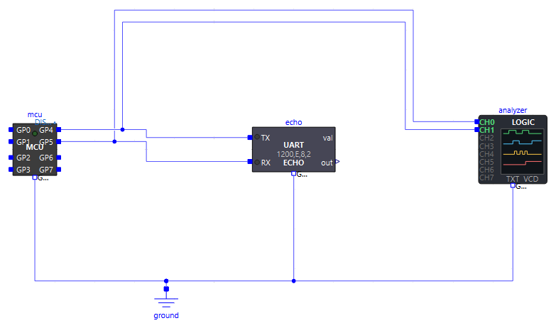
To read a serial frame, an I2C transaction or a word of an HX711 byte by byte, rather than by pointing at a curve in OMEdit, the library provides a logic analyser probe: Peripherals.Analyzers.LogicAnalyzer. It observes without driving anything: its inputs have a 1 GΩ impedance, the circuit behaves the same with or without it.
At the end of the simulation, it writes its files in the simulation folder (full paths in the log):
| File | Contents | To read it |
|---|---|---|
<component name>.txt |
Decoded bytes in hexadecimal + ASCII, then an ASCII timing diagram of the channels, with bits and bytes under each decoded signal | Notepad, opened automatically (openText) |
<component name>.vcd |
Recording of the levels (Value Change Dump) | PulseView or GTKWave |
<component name>.pvs |
PulseView session: the protocol decoders already set up from the channels | PulseView, which loads it by itself with the VCD file |
Connecting the probe
Connect channels CH0…CH7 to the wires to observe and GND to the ground of the circuit (or uncheck useGroundPin: the pin disappears and the probe is referenced to the simulation ground); an unconnected channel reads 0. Each channel is set up in its own tab (CH0…CH7): a name and a kind. By default, CH0 to CH3 are active (Logic) and CH4 to CH7 are off (Off): the pin of an Off channel disappears from the icon, and the names of the active channels are written in green on it. To use CH4…CH7, give them a kind.
Kind (chNKind) |
For | What the probe does with it |
|---|---|---|
Off |
Unused channel | Nothing: not recorded, costs nothing, and its pin disappears |
Logic |
Any level (LED, button, PWM) and any clock line (SCL, PD_SCK, SCK) | Recorded, drawn; summary of its edges and duty cycle |
Uart |
One wire of a serial link | Decoded with the format of the tab: speed, bits, parity, stop bits, bit order |
I2cSda |
The SDA line of an I2C bus | Decoded, SCL being the channel chNClockChannel |
SyncData |
The data of a synchronous serial link (HX711, simplified SPI) | Read on an edge of the channel chNClockChannel, in words of chNWordBits bits |
The data channel names its clock channel: SCL stays a Logic channel. One probe can thus follow two buses.
MicroPythonMCU.Peripherals.Analyzers.LogicAnalyzer analyzer(
  ch0Name = "SCL",                                              // Logic by default
  ch1Kind = MicroPythonMCU.Interfaces.ChannelKind.I2cSda, ch1Name = "SDA", ch1ClockChannel = 0,
  ch2Kind = MicroPythonMCU.Interfaces.ChannelKind.Off,          // CH2 and CH3 turned off by hand,
  ch3Kind = MicroPythonMCU.Interfaces.ChannelKind.Off);         // CH4 to CH7 are off by default
...
connect(analyzer.CH0, mcu.GP4);
connect(analyzer.CH1, mcu.GP5);
connect(analyzer.GND, ground.p);
The text file
Decoded bytes (hex + ASCII)
One section per decoded channel: the bursts of a UART channel (bytes less than two frame durations apart), sixteen bytes per timestamped line; one line per I2C transaction; one synchronous word per line. Logic channels get a summary.
TX  burst 1  5.000 ms .. 155.000 ms  15 bytes
      5.000 ms  48 65 6C 6C 6F 2C 20 70  61 72 69 74 79 21 0A      |Hello, parity!.|
RX  burst 1  13.750 ms .. 163.750 ms  15 bytes, 15 with error (!P parity, !F stop bit low)
     13.750 ms  48!65!6C!6C!6F!2C!20!70! 61!72!69!74!79!21!0A!     |Hello, parity!.|

SDA  I2C, clock SCL  3 transactions   (* = not acknowledged, NACK)
      1.003 ms  S [42 W] 48 65 6C 6C 6F 20 49 32 43 P   |Hello I2C|
      1.918 ms  S [42 R] 48 65 6C 6C 6F 20 49 32 43* P   |Hello I2C|
      2.833 ms  S [42 W] 5A Sr [42 R] 5A* P   |ZZ|
LED7  logic, 1 edge (1 rising), first at 3.215 ms, high 67.8 % of the time

DOUT  synchronous data, clock PD_SCK  6 words of 24 bits
    400.005 ms  068DB9 = 429497   + 1 extra clock pulse
!after a UART byte: wrong parity (!P) or low stop bit (!F). The byte is kept, as the RP2040 receiver does.- I2C:
[42 W]is the address and the direction,Sra repeated START,*a byte not acknowledged. The last byte of a read is never acknowledged: that is how the master ends it. - Synchronous serial: the word in hexadecimal and in decimal (signed if
chNSigned). Clock pulses beyond a word are counted: the HX711 adds 1 to 3 of them to select the gain of the next measurement.
Timing diagram
Each channel is drawn on two lines: _ at the top for the high level, _ at the bottom for the low level, | for an edge. Under a decoded channel come the bits one by one, then the value of each byte in brackets:
=== frame 1   5.000 ms .. 163.750 ms

  4.167 ms
           __         _     _     ___   _   _     ___     ___       ___   ___
  TX         |_______| |___| |___|   |_| |_| |___|   |___|   |_____|   |_|   |___|
              S 0 0 0 1 0 0 1 0 P s s S 1 0 1 0 0 1 1 0 P s s S 0 0 1 1 0 1 1 0 P
             [       48 H       ]    [       65 e       ]    [       6C l       ]
           _______________________         _     _     ___   _   _     ___     ___
  RX                              |_______| |___| |___|   |_| |_| |___|   |___|
                                   S 0 0 0 1 0 0 1 0 P s s S 1 0 1 0 0 1 1 0 P s s
                                  [       48 H       ]    [       65 e       ]
- UART:
Sstart, the data bits in transmission order (least significant first:48=0 0 0 1 0 0 1 0read backwards),Pparity,sstop. - I2C: the bits read at each rising edge of SCL,
A/Nthe acknowledgement,S,Sr,P(STOP). - Synchronous serial: the bits read on the chosen edge, then the word.
A frame starts on a new line, under a === frame n header. A frame is a UART burst, an I2C transaction or a burst of clock pulses; two overlapping frames make one, like the message and its echo here. A silence longer than textSilence is not drawn, a line gives its duration:
A line is only cut at an instant when no channel is in the middle of a byte. It is textWidth columns wide, each worth textResolution. By default the resolution is half a bit of the fastest UART and half a level of the fastest clock (2.5 µs for a 100 kHz SCL).
The VCD file and PulseView
VCD is the format opened by logic analyser software. It only holds the channels that are not Off, with their names. Next to it, the probe writes a PulseView session (.pvs, same name): PulseView loads it by itself when it opens the VCD file, whether the probe or the student opens it by hand. The decoders are already set up from the channels, there is nothing to configure:
| Channel | PulseView decoder |
|---|---|
Uart |
UART on this channel (RX), with the speed and format of the tab, bytes shown in ASCII |
I2cSda |
I2C, SCL = its clock channel, SDA = itself |
SyncData |
SPI, CLK = its clock channel, MISO = itself; clock polarity read at the start of the capture, phase derived from the reading edge, word size |


- Get PulseView, without installing anything: double-click
get_pulseview.cmd, at the root of the downloaded folder (next toMicroPythonMCU). The script downloads a portable copy of PulseView (about 25 MB), checks its fingerprint and unzips it into aPulseViewfolder next to the library. It needs no administrator rights and only uses tools that come with Windows 10 and 11. - Tick
openPulseView: PulseView opens on the file at the end of the simulation. Otherwise, open it by hand from PulseView's open menu, Import Value Change Dump data…, choosing the.vcdfile whose path the log gives. - Without a session (
writePulseViewSession = false), add a decoder yourself (Add protocol decoder button) and set it up by clicking on its label:- UART: RX channel = the wire to decode, Baud rate, Data bits, Parity, Stop bits identical to the program's (
UART(0, baudrate=1200, bits=8, parity=0, stop=2, ...)→ 1200, 8, even, 2); - I2C: SCL and SDA channels.
- UART: RX channel = the wire to decode, Baud rate, Data bits, Parity, Stop bits identical to the program's (
pulseViewPath stays empty, except in special cases: the probe looks for PulseView by itself, in this order, and takes the first one found:
| Order | Location | For whom |
|---|---|---|
| 1 | The environment variable MICROPYTHONMCU_PULSEVIEW: path of pulseview.exe or of its folder |
A classroom: a single copy on a network share, the variable set once per computer (setx MICROPYTHONMCU_PULSEVIEW "\\server\software\PulseView") or by the administrator |
| 2 | The PulseView folder next to MicroPythonMCU, filled by get_pulseview.cmd |
A personal computer |
| 3 | C:\Program Files\sigrok\PulseView\, where the installer from sigrok.org puts it |
A computer where PulseView is already installed |
Not found: a warning in the log gives the paths tried, and the simulation ends normally. A non-empty pulseViewPath bypasses the search.
PulseView names the channels probe.TX, probe.RX… (the prefix is the section of the VCD file). PulseView's SPI decoder knows nothing of bursts: clock pulses beyond a word (HX711 gain) shift its next words, whereas the text file counts them apart. GTKWave also opens the VCD file, for the timing diagram alone (no protocol decoder).
Parameters of LogicAnalyzer
General tab:
| Parameter | Default | Role |
|---|---|---|
fileName |
"" |
Base name of the files (<base>.txt, <base>.vcd); empty: component name |
writeText |
true |
Writes the text file |
openText |
true |
Opens it in Notepad at the end of the simulation |
writeVcd |
true |
Writes the VCD file |
writePulseViewSession |
true |
Writes the PulseView session next to it (<base>.pvs), decoders set up from the channels |
openPulseView |
false |
Opens it in PulseView at the end of the simulation (a warning if PulseView is not found) |
pulseViewPath |
"" |
Path of pulseview.exe: absolute, relative to the simulation folder, or modelica:// URI; empty: automatic search (variable MICROPYTHONMCU_PULSEVIEW, copy from get_pulseview.cmd, sigrok installation) |
Tabs CH0 … CH7, one per channel (chN = ch0 … ch7); the settings that do not apply to the chosen kind are greyed out:
| Parameter | Default | Group | Role |
|---|---|---|---|
chNKind |
Logic for CH0…CH3, Off for CH4…CH7 |
Channel | Kind of the channel (table above); Off removes its pin |
chNName |
"" |
Channel | Name in the files, without comma; empty: CH0, CH1… |
chNBaudrate |
1200 | UART | Speed |
chNDataBits |
8 | UART | Data bits, from 5 to 8 |
chNParity |
None |
UART | None, Even or Odd |
chNStopBits |
1 | UART | 1 or 2 |
chNUartBitOrder |
LsbFirst |
UART | Bit order (a UART sends the least significant bit first) |
chNClockChannel |
previous channel (CH1 for CH0) |
Clock | Number of the clock channel of an I2cSda or SyncData channel, itself of kind Logic |
chNClockEdge |
Rising |
Synchronous serial | Edge on which the data is read (HX711: Falling) |
chNWordBits |
8 | Synchronous serial | Bits per word, from 1 to 32 (HX711: 24) |
chNSyncBitOrder |
MsbFirst |
Synchronous serial | Bit order |
chNSigned |
false |
Synchronous serial | Two's complement words (HX711: true) |
Text file tab:
| Parameter | Default | Role |
|---|---|---|
textHexDump |
true |
Section of the decoded bytes in hex + ASCII, and summary of the logic channels |
textWaveform |
true |
ASCII timing diagram |
textBitLabels |
true |
The bits one by one under each decoded signal, above the bytes |
textSplitFrames |
true |
Each frame starts on a new line, with a header |
textCompressSilences |
true |
A silence longer than textSilence is not drawn |
textSilence |
0 | Shortest silence that is not drawn; 0: automatic (40 columns) |
textResolution |
0 | Duration of one column; 0: automatic |
textWidth |
100 | Columns of timing diagram per line |
Electrical tab:
| Parameter | Default | Role |
|---|---|---|
VIH, VIL |
2.0 V, 0.8 V | The level changes halfway, (VIL + VIH)/2 = 1.4 V, as for the microcontroller |
GIn |
1e-9 S | Input conductance of each channel to ground (1 GΩ) |
useGroundPin |
true |
Shows the GND pin. Unchecked: the probe is referenced to the simulation ground (0 V, common to every Ground block), nothing to wire |
Good to know
- Cost: one threshold-crossing function per channel that is not
Off. On a wire that already changes at events of the model (output of the microcontroller or of a device), the probe adds no event. The text file is written at the end, from the edges kept in memory. - The probe sees the electrical edges, about a hundred nanoseconds after the command (charging of the input capacitances). VCD times are in nanoseconds.
- A level that changes and changes back at the same simulated instant (Modelica event iterations) is not recorded.
- Limits: 2 million edges kept for the text file (the VCD file is complete); 200,000 columns of timing diagram, about 2000 lines. A fast PWM over a long simulation gets there quickly: raise
textResolution, or keep only the hex section (textWaveform = false). - A resolution coarser than the bits distorts the drawing (missed edges), but not the decoding, which reads each bit from the edges themselves.
- Examples:
Analyzer.UartLink(serial link),Analyzer.UartErrors(same link, misconfigured device),Analyzer.I2cBus(I2C bus),Analyzer.Hx711Serial(synchronous serial).